资源说明:ATtiny85 based micro controller project that replicates the functionality of an Apple remote control along with a simple hardware design for the remote control.
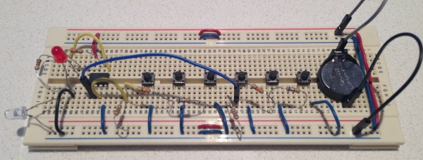
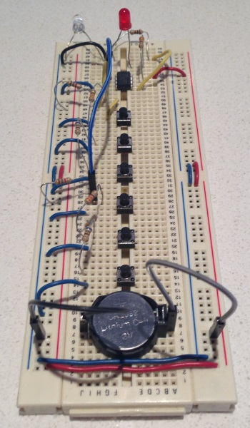
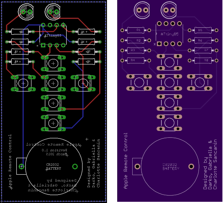
### Overview ATtiny85 based micro controller project that replicates the functionality of an Apple remote control along with a simple hardware design for the remote control. ### Apple Remote/ NEC Protocol Overview - The Apple Remote uses an NEC IR protocol which consists of a differential PPM encoding on a 1:3 duty cycle 38 kHz 950 nm infrared carrier. - Remote commands are 32 bits long, in the format : remote id (8bits), command (8 bits), apple identifier (16 bits) - The 32 bits of encoded data are sent between the leader and the stop bit (time in microseconds): - leader: 9000 on, 4500 off - 0 bit: 560 on, 1690 off - 1 bit: 560 on, 565 off - stop: 560 on - More information at http://en.wikipedia.org/wiki/Apple_Remote and http://www.sbprojects.com/knowledge/ir/nec.php ### Implementation Overview - This code uses a 50% duty cycle for the PWM (instead of the standard 1:3) for simplicity which still works. - PWM is done using 'Clear Timer on Compare Match (CTC) Mode'. [Page 72] 11.7.2 describes CTC mode. - Output is on 0C0A which is PB0. The internal clock is set to run at 8Mhz. - No prescaler is used. @8Mhz 1 tick = .000000125 secs, 38khz is a cycle every .000026 secs. - This means there is 208 ticks required for a full cycle (.000026/.000000125). OCR0A is set to half of this at 104. - This is half a full cycle, meaning it will be off for a half cycle, toggled due to COM0A0, and then on for a half cycle. - We enable/disable PWM by enabling toggle on compare mode and then disconnecting OC0A and assuming normal port operation. [Page 78] - The buttons are setup in a voltage ladder (http://en.wikipedia.org/wiki/Voltage_ladder). They are triggered via interrupts on PB4 and PB3 and each button is identified via a ADC conversion. - The MCU is set to sleep in the main loop (using SLEEP_MODE_PWR_DOWN mode) and is only awoken using pin change interrupts. ### Button Voltage Ladder Values Voltage ladder values (using 10 bit ADC resolution) on PB4 RIGHT: 0.00V @ 5V / 0.00V @ 3V / 0 (1.8K) DOWN: 0.77V @ 5V / 0.46V @ 3V / 158 (330R) MENU: 1.78V @ 5V / 1.08V @ 3V / 367 (680R) Voltage ladder values (using 10 bit ADC resolution) on PB3 UP: 0.00V @ 5V / 0.00V @ 3V / 0 (1.8K) LEFT: 0.77V @ 5V / 0.46V @ 3V / 158 (330R) SELECT: 1.78V @ 5V / 1.08V @ 3V / 367 (680R) ### Schematic  ### Breadboard   ### PCB Layout  ### Final Product 
本源码包内暂不包含可直接显示的源代码文件,请下载源码包。
 English
